
 By Patricia Maxwell/photos by the author
Burton Maxwell developed an early interest in logging, a passion fueled by the proximity of the mountain railroads in the Sierras that rose out of the San Joaquin Valley where he and his family lived. Tuolomne City and the West Side Lumber Company were near, yet far, to a farm kid tied to a daily milking schedule.
Nevertheless, one or two exposures to logging operations and Burton was hooked. He dreamed of building a model railroad where not only trains moved, but all the equipment, as well. In the intervening years, he has accomplished that.
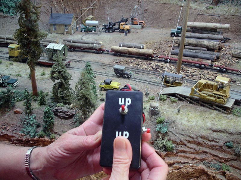
His layout of the West Side Lumber Company showcases three areas where logging equipment operates. His “Buffalo Landing” scene includes a spreader bar loader which picks logs off log trucks, carries them by cable to log cars where they are dropped into place for the train trip to the mill. There are two kinds of loaders: the spreader bar and the crotch line. Burton chose to build the spreader bar loader because it is a little simpler to build than the crotch line loader. Buffalo Landing has only one logging donkey, but there’s a lot going on. There are always two or three loaded log trucks grinding down a dirt road into the area that is crossed by the main rail line plus a siding. It has taken lots of time and ingenuity to make models that move but it all started by seeing the prototypes, reading books, looking at pictures and hiking the abandoned road beds of the West Side. Seeing, walking and photographing the area has given him a feel for how to make realistic looking models.
This article will focus on the Buffalo Landing section, though the basic principles apply to the other two areas. Burton decided he needed a space at least 6′ by 2½’ to adequately build Buffalo Landing. Now, he wishes he’d built it a foot longer. With the dimensions in mind, he drew plans, then redrew them five or six times. The locations for the spar poles and logging donkey can be seen in the accompanying track plan. Once the plans were drawn to his satisfaction, he took inventory of his supplies. For Buffalo Landing, he needed two geared motors, two spar poles, a logging donkey and an electrical mechanism to make the whole thing operate.
The next thing on the agenda was building a frame of 1×4. He wanted to expand one end to make it wider and the drawing mentioned above will show you how he did that. Once he got the framing in, he laid the track. Next, he built the foundations for the two spar poles and the logging donkey. Then it was time to form the basic scenery shapes. He used cardboard strips woven into a lattice. Over this he hot-glued small squares of mineral paper obtained from the hardware store. The mineral paper squares can also be dipped in white glue and spread over the cardboard. On top of this foundation, he spread a mixture of half Fix-It-All and half sawdust as a base coat. Once this dried, he began to shape the areas with additional Fix-It-All and sawdust…
You can read the rest of this story in the 2009 HOn3 Annual.
![]()
Download the Buffalo Landing framing diagram
Requires FREE Adobe Acrobat Reader software.